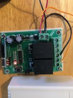
Hi. I bought a RC model some years back which had a transceiver with two buttons: A and B. On the receiver, which seems limited to 9 Volts because 12 volts doesn’t work, I have two electricity pins (one for positive and one for negative) and then finally I have 6 pins, 3 for each relay switch. Each relay switch offers the following pins: NO1, COM, NO2, NC1, COM, NC2.
When I connect a 9 volt battery to the chip, a red led light lights up correctly, and depending upon what choices I select I can see and sometimes hear the relay switch working. My problem is that I don’t know what wires to connect to the relay switch. I guessed that I would connect to NC1 and NC2. This makes the relay switches emit led lights and a clicking sound. However, this does not open any 9 V electrical circuit. Can you tell me how to connect my wires to these switches in order to make the remote control work?
Also, I read that COM means COMMON. What is that even used for? I understand what NC and NO means but not com.
Any help is appreciated.